|
ARTICLES & HOW-TOS |
Interpreting Line Drawings for Ship Modelling
Russell Barnes
One the members asked if I would write a few words about interpreting lines drawings and using them in ship modelling. Actually, I wrote a bit about this over on Dry Dock Models, so rather than reinvent the wheel again, I will repost the relevant material here for anyone who is interested.
This subject might be of interest to those of you who wish to learn a bit more about scratch building or kit bashing. I will approach it in parts, and even so, I will only be going over the basics so there will be questions about lines drawings that I do not cover.
First, let us take a Model Shipways plan as an example. It has been redrawn, probably from some original source. There are three drawings in a set of lines. There is the sheer profile (side view), the half breadth, (looking down through the top or up through the bottom at one side of the hull), and the body plan (view down the middle of the hull using one half of each cross section).These drawings have been faired, meaning that the draftsman has gone through the drawing and worked it out so that all three drawings agree with each other and produce a smooth hull. If there is any discrepancy in any of the drawings at any point, then the plan is not fair and will not produce a usable set of frames from which one could build a model.
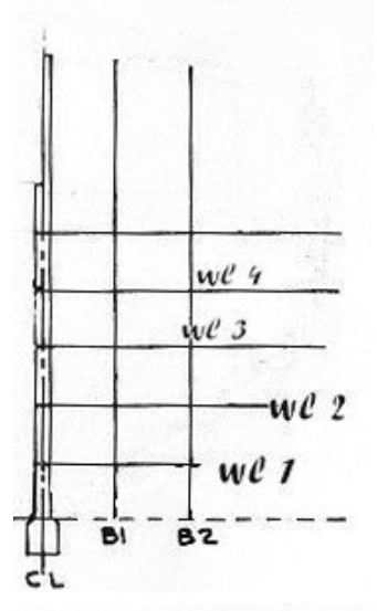
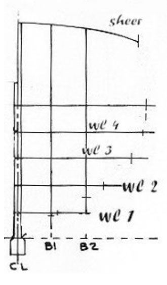
Now, the first drawing to look at is the sheer profile. This side view gives you the general outline of the hull, but there are also some other important architectural lines to address. There are the waterlines (not to be confused with the hull's load waterline) that run along the hull horizontally. These are sometimes referred to as level lines or, in the case of a solid hull model, lift lines. Then there are some curved lines that run along the length of the hull called buttock lines. The key to a drawing like this is that these lines appear in each of the three drawings, they just look different because of the different aspect of each drawing.
Look at the half breadth. You will see a centreline, from which all horizontal measurements are taken. Out from the centreline you will see a series of curved lines. These are those same waterlines we saw in the sheer profile, they are just seen from the bottom up rather than from the side. In the half breadth, you will also see some straight lines that are placed out from the centreline at even spacing. These are those same buttock lines we saw as curved lines in the sheer profile. Again, we are seeing them from a different aspect. Also, in the half breadth, the line of the deck and the line of the railing will show up as curved lines, almost like waterlines. These are important for developing the cross section shapes in the upper part of the hull.

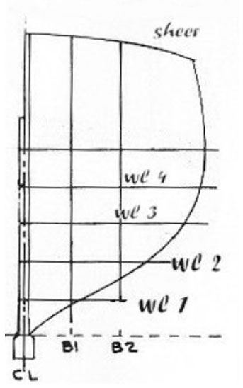
Now, look at the body plan. The cross sections are laid out on a grid. On the right side we have the cross sections from the forward part of the hull back to the midsection. On the left side we have the cross sections in the aft part of the hull going forward to the midsection. Now, note the horizontal lines in the grid. The bottom line is the base line. You will see the base line drawn on the sheer profile. This is the line from which all vertical measurements are taken. Above that you will see other evenly spaced horizontal lines.
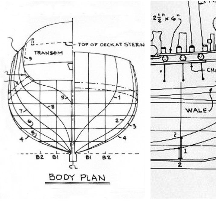
These are the waterlines we saw as straight lines in the sheer profile and as curved lines in the half breadth. There are also the vertical lines to be noted. The one in the middle is the centreline we saw in the half breadth, from which all horizontal measurements are taken. Out from the centreline, we see evenly spaced vertical lines. These are the buttock lines we saw as curved lines in the sheer profile and straight lines in the half breadth. You will also see curved lines running along the cross sections giving you the line of the deck and the line of the railing.
Okay, we have the lines and we know what each of the principle lines is and we have learned a bit about how it relates to the drawing. But we need more information to proceed.
Note on the lines drawing those vertical station lines on the sheer profile. Those represent the cross sections from the body plan that are also seen as straight lines in the half breadth plan. Measurements were taken at each station line on both the half breadth and the sheer profile to create those cross sections in the body plan that represent the shape of the hull.
Now, here is an important bit of information. We know that the curved buttock lines in the sheer profile are represented as straight lines in the body plan and half breadth. Also we know that the curved waterlines of the half breadth are represented as straight lines in the body plan and sheer profile. We know that the curved cross section shapes of the body plan are represented as straight lines in the sheer profile and half breadth. But which buttock line is which? How do we determine which line in the sheer profile or half breadth relates to what line in the body plan?
Here is how. On the body plan, the forward most cross section is the curved line closest to the vertical centreline. As you go outward in the forward cross sections, you will see they get slightly larger as we approach the midsection. Conversely, from the stern, the cross sections get larger as they approach the midsection. You will see that the numbers for the cross sections in the body plan correspond with the station line numbers in the sheer profile and half breadth.
Now, follow closely.
 Note that on the sheer profile, we have two buttock lines. The lowest one is the closest one to the centreline of the hull. The next higher buttock line is further away from the centreline.
The same goes for the waterlines, except that the one closest to the centreline in the half breadth is the lowest one in the sheer profile and the body plan. The next wider half breadth waterline is the next higher one in the sheer profile and the body plan and so forth. Now, there is an exception in the case of the water lines. As you go higher on the hull, the hull has a tumblehome, that is the upper sides of the hull curve inward towards to the centreline so that the rail and maybe even the deck is closer to the centreline than the widest part of the hull. As a result, in the half breadth, the line of the rail and deck may appear to be closer to the centreline than the waterlines lower in the hull. Well, don't worry, you'll pick up on that when we plot a cross section.
You can use the stations that have been plotted for you to build the model's bulkheads but if you wish to use your own that do not correspond to what is already drawn, you can do that too. But how? When you finally get it, you will smack yourself upside your head and say "DOH!!" Trust me, its not rocket science.
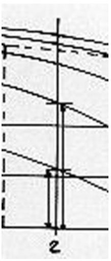
First let's take one of the cross section stations that is already in the plan and plot its measurements to see how it is done. Let's take station 2 up forward for instance. Remember, on the sheer profile drawing, all measurements are taken vertically from the base line up and all the measurements on the half breadth are from the centreline out. Now, you can use a pair of dividers to take these measurements, but I used to do that and was never quite sure the points of the dividers were right on the lines I wanted to measure. So, I switched to using a tick strip. Its just a piece of paper or card stock. Lay a piece of paper on the sheer profile so that it is arranged right on the station 2 vertical line. Make sure it also intersects the base line. Now, place a mark on the paper where it crosses the base line. Now, make a mark on each buttock line at station 2 and mark them so you remember which is which. Now, take that tick strip over to the body plan and lay it down so that the base line mark is lined up on the base line of the body plan and the strip is aligned vertically with the buttock line closest to the centreline. The first buttock line mark you made on the sheer profile should line up with where cross section 2 intersects the first buttock line. Next, move the strip outward along the base line of the body plan so that it lines up with the second buttock line. If all the marks are aligned, the second buttock line mark you made should meet cross section 2 where it intersects the second buttock line.
Now, take another tick strip and locate cross section station 2 on the half breadth. Make a mark on the centreline and then mark where the waterlines intersect cross section 2. Now, go back to the body plan and line up the tick strip horizontally so that it intersects with the centreline and the lowest waterline. The first mark you made should show where cross section 2 intersects the lowest waterline. Now, move the strip upward to the next waterline and repeat the operation and so forth. For the deck line and the railing, move the strip up where it is roughly at the same height above the base line as the railing at section 2. Align the mark for the centreline and the mark for the railing should be right on section 2. You can also cross check these height measurements on the sheer profile by measuring upward at station 2 from the base line to the deck and the rail just as you did when measuring the heights of the buttock lines and then compare the deck rail heights with the deck and rail heights of cross section 2 on the body plan.
Well, now you know what the lines mean and how they relate to one another. But what about actually drawing your own frames?
This is the easiest part, once you know what all those lines are for. First, choose where in the hull you want your frame. It can be anywhere. Rule a line perpendicular to the sheer profile base line and the half breadth centreline. Most lines drawings are arranged with the sheer profile and half breadth one above the other so just rule the line at right angles to the sheer profile base line and the half breadth centreline. That is your new station line.
Next, make a tracing of that grid in the body plan. Include the base line, the centreline, the buttock lines, and the waterlines. These are all your important reference lines. It has been my experience that you cannot be accurate measuring off the grid and drawing it. No matter how carefully you measure, the reference lines might be slightly off and that will throw the frame shape out of whack.
Now, with your dividers or tick strip, take your measurements from both the sheer profile and the half breadth for your new frame, just as you did in the sample frame we measured off. Be sure to measure off the height of the deck and underside of the railing for your new frame when you are measuring off the sheer profile drawing. With a tick strip all these measurements can be gotten at once rather than going back and forth using dividers.
Transfer your measurements to the grid you traced. Mark the reference points on both sides of the grid so you can plot out the full frame. Be sure to include the thickness of your keel on the grid where the frame meets it. Draw in half the keel's thickness on either side of the centreline in the grid. This way, you will have the true shape of the frame. If you extend your frame right into the centreline, it could end up distorting the bottom of the frame when you go to cut it out. There is often a decidedly different angle down there using the hull's centreline from what you would get including the thickness of the keel.
When once you have all your reference marks in place, use a French curve or ship's curves if you have them to connect all the dots. Do not worry so much if the shape does not seem to flow in a simple curve as you imagine it might. Some hull shapes demand several different kinds of curves for the entire hull frame. If you have measured carefully and been careful setting up the grid, then your frame should be okay, provided the lines drawing you worked from is fair. You may find that there are slight discrepancies to overcome, but this is normal. When in doubt leave the frame a tad full, so you can fair out the differences later on when you cut the frame and install it.
 By the by, how do you find the bevel of a given frame? Its easy. On your sheer profile and half breadth plan, draw a line parallel to your frame station line that represents the thickness of your frame. Now, measure this frame and transfer those measurements to your frame drawing just as you did with the station line. Connect those dots and you will see a slightly different curve represented. This is the bevel of your frame. Laying out bevels may not be necessary so much in the middle of the hull where the changes in the shape of the hull are slight, but in the ends where the changes become more drastic, it is a good guide to have when fairing your hull. Remember, the beveled side of the frame is forward of the station line in the forward section of the hull and aft of the station line in the after part of the hull.
Well, there you have the basics. If you have a lines drawing with your kit and you wish to add more bulkheads, you can now determine the shape of those bulkheads. This is not everything you need to know to go off and scratch build, but it is a start.
|
© 2023 The Nautical Research Guild, Inc. Nautical Research Guild ® and the NRG logo are Registered Trademarks, and belong to the Nautical Research Guild (United States Patent and Trademark Office: No. 6,999,236 & No. 6,999,237, registered March 14, 2023)
|
![]()
© 2020 The Nautical Research Guild, Inc.
![]()